|
CMPSCI
- 503 Embedded
System Widget
Interface Standard (WIS) Initial Release 1.00 |
|
|
Author: Andrew
W. Wolan |
Version: 1.00 Date: 12/03/2003 |
|
Notes: This specification is for all practicallity complet. Things may
change, but I am doubtful, because many aspects have matured. |
|
1 - Introduction................................................................................................................................. 3
2 - Connector Specification............................................................................................................... 4
Introduction................................................................................................................................... 4
Pin Assignment.............................................................................................................................. 5
Cabling......................................................................................................................................... 6
3 – Hub Specification........................................................................................................................ 8
The Concerns of an I2C Network of Widgets................................................................................ 8
The Hub - A Solution to the Networking Problem.......................................................................... 8
Hub Design................................................................................................................................... 9
4 – Widget/Network Connectivity & Topology................................................................................ 11
Introduction................................................................................................................................. 11
Widget to Hub............................................................................................................................ 11
Widget to Widget........................................................................................................................ 11
Hub to Hub................................................................................................................................. 12
5 – Wiring a Widget for WIS........................................................................................................... 13
General Guidelines....................................................................................................................... 13
Self-Powered Widgets................................................................................................................ 13
6 –Constraints................................................................................................................................. 15
Network Constraints................................................................................................................... 15
Hub Constraints.......................................................................................................................... 15
List
Of Figures
Figure 1 – Pin Location
on the Connectors......................................................................................... 4
Figure 2 – Pin /
Function Mapping..................................................................................................... 5
Figure 3 – Summary of
Data from Figures 1 and 2............................................................................. 5
Figure 4 – Diagram of a
Connector Cable Illustrating Pin-Outs and Twisted Pairs............................... 6
Figure 5 – Wiring
Diagram for the Hub............................................................................................ 10
Figure 6 – Widget to
Hub Topology................................................................................................ 11
Figure 7 – Daisy
Chaining................................................................................................................ 12
Figure 8 – (Top)
Daisy-Chain Topology (Bottom) Star Topology..................................................... 12
Figure 9 – Wiring a
Widget to Support WIS.................................................................................... 13
Figure 10 – Network
Constraints..................................................................................................... 15
Figure 11 – Hub
Constraints............................................................................................................ 15
1 -
Introduction
The following is a preliminary draft for the Widget Interface Specification (WIS). This specification proposes a standard which to interface devices that use the I2C communications protocol developed by Phillips Semiconductors.
This draft is a “work in progress” and is subject to change without notice.
2 -
Connector Specification
The Widget Interface Specification (WIS) consists of two types of connectors: a male connector and a female connector. The gender of the connector is determined by how it connects to a mating connector. The male connector uses a 6-pin connector with 5-prongs for conductivity. Each prong is a male prong. Likewise, the female connector uses a 6-pin connector with 5-prongs, each of which is female. (This convention was made to make it easy to remember: male connector - male-prongs, female connector - female prongs.)
In terms of functionality, when connecting a widget to another widget (or a hub), the female connector is considered to the be the “source” for both the power and electrical interface to the network bus. The male connector is considered to be the “destination” for both power and the electrical interface to the network bus. Another way of expressing this functionality is that the female connector is the “output” while the male connector is the “input”.
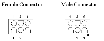
A pin diagram of the female and male connectors (respectively) are shown in Figure 1. The diagram assumes that the connector is viewed from the pin end of the connector. Note the location of the notch in the diagram.
|
|
|||
Obviously, each pin on the male and female connector has a purpose. The table in Figure 2maps each pin to its function and corresponding wire color.
|
|
|||
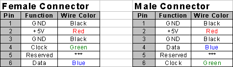
It shall be stated that the coloring scheme is only a recommendation. What is important is that the correct signals are applied (or drawn) from the appropriate connectors.
The reason why there are two ground connections is explained in the following section entitled “Cabling”.
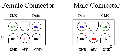
The following diagram summarizes the information in Figures 1 and 2 so it will be a useful aid to those wiring a connector by hand.
|
|
|||
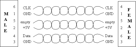
When connecting a widget to a remote widget, a cable of some length will obviously be needed. If your cable is going to be longer than a foot, it is highly recommended that CAT5 cabling be used. A CAT5 cable consists of 3 twisted pairs 23 gauge copper wiring.
Long runs of wire are susceptible to extern electrical interference. This electrical interference can degrade the Data and Clock signals on the network bus. Furthermore, the Data and Clock lines can induce a signal on each other, introducing “cross-talk”.
To minimize these effects, the Data lines is twisted with the ground wire in one twisted pair of wiring while the Clock signal is twisted with the other ground wire. This configuration helps protect the signals from extern interference while isolating them from each other to minimize the effect of cross-talk.
A wiring diagram for a connector cable is shown in Figure 4. Notice how the Clock and Data signals are each twisted with a Ground wire while the 5V wire is twisted with a functionless wire.
|
|
|||
|
Figure 4 – Diagram of a Connector Cable Illustrating Pin-Outs and Twisted Pairs |
For simplicity, there is no pin-to-wire mapping for a cable. This simplification acknowledges the fact that a widget designer is primarily concerned with the wiring of their widget to a connector. The designer only cares if the pin on the mating connector carries the correct signal. As a result, the user is free to assign whatever color wire they want to a signal, as long as they are consistent on both end of the connector and that the following two rules are obeyed:
1) The Data and Clock signals are twisted with their own ground wire
2) The length of the ground wires in the cables are of the same relative length
If the lengths of the two ground wires are mismatched, the potential across each line will be different. Thus, some the current coming out of the higher potential end will be attracted by the lower potential end and the current will loop back, creating a classic current loop. Keep the length of the ground wires in the cables the same relative length to minimize this effect.
Note: the ideal solution for carrying the Data and Clock signals would be to use differential signaling. However, such a system would
1) Complicate the network wiring structure,
2) Would be an overkill for our application, in terms of our environment.
If the cablings between two widgets is less than a foot, you can simply use regular wire. It is recommended that you twist the Data and Clock signals to their own ground wire.
3 – Hub Specification
The Concerns of an I2C Network of Widgets
There are three primary concerns that are encountered when developing an I2C network. The first is in regards to the pull-up resisters. Lets say that we agree on using a 220 ohm pull-up resister for the I2C network, yielding a current of 23mA. (5 / 220 = 23m) If two widgets are supplying the pull-up resisters to the bus, then what we have are two 220 ohm resisters running in parallel from the 5-volt supply to the bus. As a result, the total resistance is halved to 11 ohm while the current is doubled to 46mA.
So, why is this doubling of current a concern? Lets say a PIC chip on the network wants to pull the Clock line to ground. If two of more widgets are supplying the pull-up resister, then instead of sinking 23mA to ground, the chip will sink 46mA. The PIC chip has a current limit of 25mA, so the doubling of current can damaged the chip. Thus, the first concern can be summarized as a “social” issue that asks the question “who will be in charge of providing pull-up resisters?” Furthermore, what if the widget in charge is removed, who takes control then?
The second concern in the design of the embedded room was power distribution. If we had a room with 20 widgets and each widget had its own DC adapter, the routing of power would become messy real quick. Furthermore, given the fact that each widget will only consume a small amount of current, (20-50 mA on average), supplying each widget with its own DC adaptor is expensive and very wasteful.
The third and final concern is supplying a common ground. In order for two devices to communicate properly using I2C, they must reference a common ground. It is possible for the ground being supplied by one DC Adapter for one circuit to be at different potential of another. By not agreeing on what potential “ground” is, the devices will not be able to communicate.
The Hub - A Solution to the Networking Problem
A proposed solution to these concerns is a device called the “Hub”. The idea is to “cluster” widgets in a portion of the room together and connect each cluster to a device called a “hub”. Each widget can either be connected directly to the hub or daisy-chained together with one end connecting to the hub. Through its connectors, the hub would physically connect the I2C busses on each widget together to form a connected network.
By making the hub a source of power, the connectors can be easily extended to carry power, thus provide a clean and elegant solution for the distribution of power, which addressed the second concern. By agreeing with the convention that that a “hub” will be in charge of providing the pull-up resisters, the first concern is resolved. Finally, since common ground connection is strung to all devices in the network, the third concern is resolved.
(If a device needs to supply its own power, it can. Refer to the section entitled “Wiring a Widget to Use WIS” for a detailed explanation.)
If the need arises where a widget connected to one hub needs to communicate with a widget on another, the two hubs can be easily daisy chained together, making one large network. Care must be taken to ensure that only one hub is providing power to the bus with pull-up resisters. This setting can be easily made via the DIP switches on each hub.
(It is worth pointing out that an “automatic” implementation using transistors is not possible.
In other words, it is not possible to isolate the currents of each cluster on the bus while at the same time be able to freely pass a logic value around the network. Several implementations using transistors were visited, but each one of them resulted in a latch that permanently held the bus to a logical ‘0’ after a device pulled the bus low and then let go. An implementation using a current limiter is possible, but difficult and expensive to implement.)
The 5-volt supplies on each hub are isolated from one another to prevent a hub from being overloaded with a demand for power. However, the ground connections to each hub remain physically connected as to provide a common ground connection to both clusters.
To summarize, the hub is to provide the following functionality:
1) Provides the necessary pull-up resisters to the I2C bus and the ability easily enable or display the pull-up resisters in case two or more hubs are connected
2) Provide a source of power to all connected widgets. (500mA max)
3) Provide a common source of ground to all devices on the network.
4) Provide connectors so widgets can connect to the hub.
5) Provide the ability to connect to other hubs for expansion.
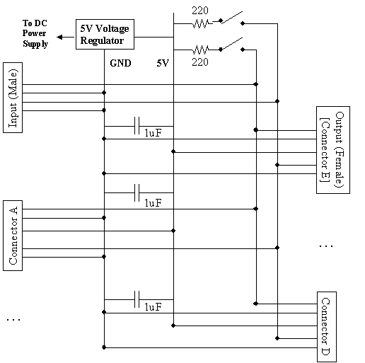
Figure X provide a wiring diagram of the hub. It shall be stated explicitly that the male “input” connector of the hub lacks a connection to the 5-volt supply. This was done to isolate the power on one hub with another.
Design Notes
- A hub is limited to providing up to 500 mA of current. This limit is the maximum output current that our voltage regular can generate. To increase the output current limit, one could use a different voltage regulator. Ultimately, the maximum amount of current that can be supplied is limited by the gauge of the wiring use. A strand of Cat 5 wire has a wire gauge of 23, which has a maximum current rating of 1 Amp. However, a current level this high is not recommended for safety reasons.
- The “Input” and “Output” connectors are intended to connect one hub to another hub.
- However, Since the “output” connector is literally just another connection to the bus, a widget can safely connect to the “output” connector of the hub as if it were a regular connector. This naming convention was only made in case this connector needs a special functionality added to it that made it unique.
- The male “input” connector is a regular 6-pin 5-prong male connector with Pin 2 (the 5-volt supply pin) removed. When connecting hubs, a regular connector cable should be able to mate with this connector without any modification.
- Connecting a widget will the male connector will not harm the widget. If connected in such a manner, the widget will not receive any power from the hub and will have to supply it own source in order for it to function.
- The 1uF capacitor is intended to decouple the 5V and GND connections from dips and minor sags in the supply power due to shifting loads on the network.
- Widgets are to be connected to the bus connectors labeled “Connector A” through “Connector E”
|
|
|||
4 –
Widget/Network Connectivity & Topology
There are three ways in which to interface a widget or hub to the I2C network:
1) Widgets to Hub
2) Widget to Widget (Daisy Chaining)
3) Hub to Hub
The following sections describe each connectivity option.
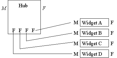
To connect a widget to a hub, merely connect one of the 5 female bus connectors on the hug to the male connector of the widget.
Due to current supply limitation, it is recommended that no more than 10 widgets be connected to one hub at a time. (23mA (bus) + 45mA a widget * 10 widget ~ 500mA) This number includes widgets that are daisy chained to the hub. Widgets connected to another hub are omitted since there are supplied by a different hub.
Figure 6 below shown a sample topology
|
|
|||
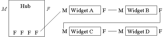
Not every widget needs a direct connection to the hub. Several widgets can instead be “daisy chained” or strung together to form a chain. One end of this chain must connect to the hub in order to receive power and to make a physically connection to the bus. The maximum length of the chain is limited to the number of widgets that can be connected to a hub.
Figure 7 shows a sample topology of a daisy chain connected to a hub.
|
|
|||
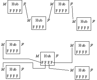
Connecting a hub to another hub is simple, but requires some care. First, select a hub that will provide the pull-up resisters and enable them on the hub. Disable the pull-up resisters on the remaining hub(s). Then, connect either the “Output” connector or one of the bus connectors (Connector A through Connector E) from one hub to the “Input” connector the other hub.
When connecting several hubs together, they can be connected in a daisy chain or some other topology. It is recommended that they be connected in a “star” topology if possible to minimize the distance from one remote widget to another.
Figure 8 below shows some sample hub topologies.
|
|
|||
|
Figure 8 – (Top) Daisy-Chain Topology (Bottom) Star Topology |
5 – Wiring a Widget for WIS
Once a I2C interface has been developed and tested on a widget, extending its design to support the WIS interface is straight-forward.
Create a male and a female connector and wire them up the widget as shown in Figure 9 below. (Refer to section one for connect pin assignments.) The male connector is intended to connect the widget to the rest of the network while the female connector will allow another widget to daisy chain off the widget and onto the network. Be sure to add the 1uF decoupling capacitor between ground and power somewhere in the circuit. This capacitor will help minimizes the effects of dips and minor sags in the supply voltage.
Though not required, it is recommended that you place a 10pF – 50 pF decoupling capacitor between the power and ground pins for each IC in your circuit. Adding such a capacitor is generally regarded a good design practice. The purpose of this capacitor is to make the IC less susceptible to minor dips in the source voltage due to the switching activity of that or some other IC in the circuit.
|
|
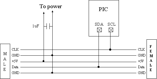
If a widget is intended to be self-powered, it is still expected to pass the +5V supply voltage and ground to the female connector. This requirement will allow a daisy-chained widget to operate. The 1uF capacitor, however, can be omitted from the widget’s circuit.
6
–Constraints
The following constraints pertain to the network.
|
|
|||
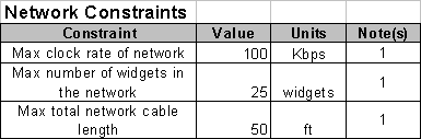
The above values assume a 25Khz clock rate which of this writing has not been tested in the lab. (However, I am highly optimistic that it will work.) The following limits can be considered a “safe mode” if the user suspect problems with the network.
|
|
|||
|
Figure 11 – “Safe Mode” Network Constraints |
Note 1: Connecting more widgets is possible, along with extending the max length of the network. Solutions range from lowering the clock rate to having multiple networks connected by an RS-232 interface. For now, lets just stick with these values.
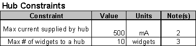
The following constraints pertain to the hub.
|
|
|||

Note 2: Value based on limit of voltage regulator.
Note 3: ![]()